Designing the USS Voyager - By Rick Sternbach.
Creating an important starship is a major undertaking that involves months of work, countless drawings,
and dozens of revisions.
 The earliest concept sketches came in September of 1993, during the last season of The Next Generation and the
second season of Deep Space Nine. Star Trek producers had already begun to plan for a new series set on a
smaller starship than the USS Enterprise NCC-1701-D, but instead
of waiting for more clarification Sternbach immediately started making sketches of this unnamed starship. Early
references came from the runabout design and others of the
saucer-engineering hell-nacelles variety, as well as from nature. Starship designs have often been inspired by
fast, sleek animals, and the USS Voyager NCC-74656 began in embryonic form
by taking on characteristics of an Ocra whale, manta ray, and a few different birds. Biological shapes were
hardened into spacecraft structures and given preliminary functions, like radiators or exotic warp stabilizers.
Following the Starfleet standard, Sternbach reserved spaces for the bridge on deck 1 and a variety of
'placeholder' crew windows about the hull, which would be built into standing sets.
The earliest concept sketches came in September of 1993, during the last season of The Next Generation and the
second season of Deep Space Nine. Star Trek producers had already begun to plan for a new series set on a
smaller starship than the USS Enterprise NCC-1701-D, but instead
of waiting for more clarification Sternbach immediately started making sketches of this unnamed starship. Early
references came from the runabout design and others of the
saucer-engineering hell-nacelles variety, as well as from nature. Starship designs have often been inspired by
fast, sleek animals, and the USS Voyager NCC-74656 began in embryonic form
by taking on characteristics of an Ocra whale, manta ray, and a few different birds. Biological shapes were
hardened into spacecraft structures and given preliminary functions, like radiators or exotic warp stabilizers.
Following the Starfleet standard, Sternbach reserved spaces for the bridge on deck 1 and a variety of
'placeholder' crew windows about the hull, which would be built into standing sets.
 Windows are an important design factor because of the coordination neccessary between various studio departments
and an outside modelmaker over continuity of the exterior of the ship and the interior. Since Voyager would
smaller, structures like windows would be proportionately larger and more visible, requiring more modeldetails
matching the stage sets. Even in the first design phase, visual effects producer Dan Curry reminded Sternbach
of the general rules of miniature design, such as making certain that motion control mount points were near the
model's center of gravity, and that the belly mount be the absolute lowest part of the ship, in order to avoid
problems with the bluescreen filming.
Windows are an important design factor because of the coordination neccessary between various studio departments
and an outside modelmaker over continuity of the exterior of the ship and the interior. Since Voyager would
smaller, structures like windows would be proportionately larger and more visible, requiring more modeldetails
matching the stage sets. Even in the first design phase, visual effects producer Dan Curry reminded Sternbach
of the general rules of miniature design, such as making certain that motion control mount points were near the
model's center of gravity, and that the belly mount be the absolute lowest part of the ship, in order to avoid
problems with the bluescreen filming.
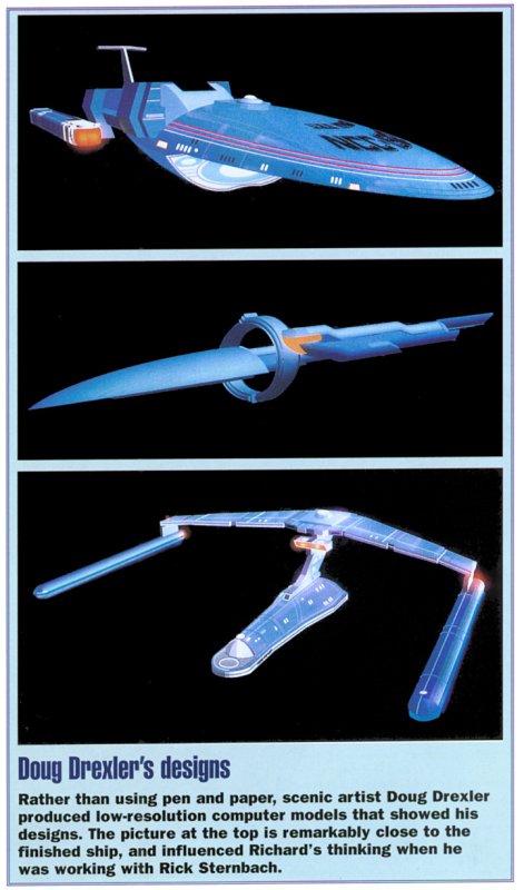
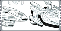
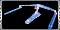
Sternbach's early sketches had Voyager as a streamlined, dart-like primary hull, with a flattened, enlongated
engineering hull, sporting swept-back runabout pylons. Later on, it was decided that Voyager would be able to
land on a planetary surface, requiring deployable landing gear and other arrangements of
 resting on hull components were sketched out. The producers also wanted some part of the ship animate or
articulate either the nacelles, or a weapon array, or perhaps the navigational deflector.
resting on hull components were sketched out. The producers also wanted some part of the ship animate or
articulate either the nacelles, or a weapon array, or perhaps the navigational deflector.
Variations filled more paper as the proportions of different parts changed, pieces were added and subtracted,
and hull contours, both gently curved and angular, were explored in perspective. Even in the rough sketches, a
lot of design idead got worked out, concerning placement of familiar items like impulse engines and phasers.
Not surprisingly, this exercise would be repeated in greater detail with each new approved version of the hull.
Preliminary hull cross-sections were drawn in blue pencil to check different internal deck heights, total number
of decks, and possibly overall ship length. Most Starfleet ships seem to have 13 feet between decks, driven
partially by set wall heights and the idea that there is a two-foot structural thickness made of deck plating,
gravity generators, and various conduits. At this stage, compared to the
 Enterprise-D at 2,108 feet, Voyager could have been anywhere from 500 to 1,200 feet long. The initial batch of
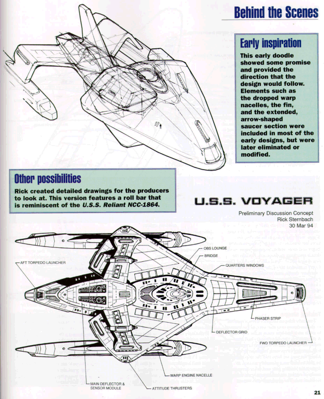
Voyager hull designs were assembled into a booklet at the end of March 1994 to give the producers a starting
point for discussion on what they liked or disliked or wanted changed. Imaginary specifications were given as:
Length: 220 meters (724 feet); Mass: 547,000 metric tons; Crew 200. A scale chart visually compared Voyager
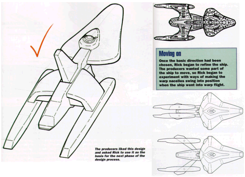
with all of the Enterprise ships. A few different schemes for nacelle articulation were suggested, including
horizontal swing-wings and a set that tucked under. In most of the 'normal' designs, it appeared as though the
primary hull could separate, though this was later elminated. The sketch that came back with a red check mark
was one of the streamlined dart ships; it drove a second round of drawings to elaborate on that basic shape.
Enterprise-D at 2,108 feet, Voyager could have been anywhere from 500 to 1,200 feet long. The initial batch of
Voyager hull designs were assembled into a booklet at the end of March 1994 to give the producers a starting
point for discussion on what they liked or disliked or wanted changed. Imaginary specifications were given as:
Length: 220 meters (724 feet); Mass: 547,000 metric tons; Crew 200. A scale chart visually compared Voyager
with all of the Enterprise ships. A few different schemes for nacelle articulation were suggested, including
horizontal swing-wings and a set that tucked under. In most of the 'normal' designs, it appeared as though the
primary hull could separate, though this was later elminated. The sketch that came back with a red check mark
was one of the streamlined dart ships; it drove a second round of drawings to elaborate on that basic shape.
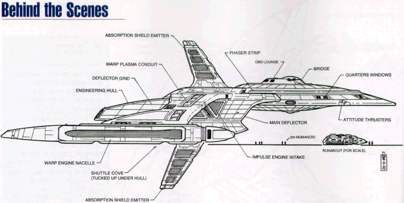
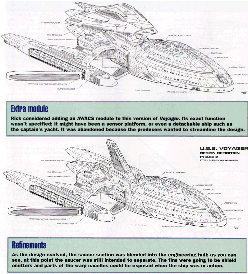
 During April and May of 1994 the first real sense of the of the new starship emerged. The slightly angular dart
front was smoothed off and nestled into the engineering sections, still assuming a separation capability, and
sweeping pylons ended in a set of long ncelles. Doors on the nacelles could open, exposing the warp coils for
some new kind of energy jump. Impulse thrusters were buried underneath, as in the runabout, and a large
triangular wedge sat atop the ship, possibly acting as a scout craft or AWACS-type of long-range sensor array.
In this design, all of the familiar Starfleet parts were added, in type and location, much the way they are now.
A few cut-and-paste variations were assembled, along with a sleeker version that left out the AWACS wedge and
combined a few shape ideas from the runabout and the
Excelsior-class. Here, a few more details crept in, notably
the large forward sensor cutout, and a stepped engineering hull that supported a ring of large cargo bays and
impulse engines. This particular variant received additional approval from the producers and proceeded to the
initial blueprint and study model stages. Sternbach scaled
During April and May of 1994 the first real sense of the of the new starship emerged. The slightly angular dart
front was smoothed off and nestled into the engineering sections, still assuming a separation capability, and
sweeping pylons ended in a set of long ncelles. Doors on the nacelles could open, exposing the warp coils for
some new kind of energy jump. Impulse thrusters were buried underneath, as in the runabout, and a large
triangular wedge sat atop the ship, possibly acting as a scout craft or AWACS-type of long-range sensor array.
In this design, all of the familiar Starfleet parts were added, in type and location, much the way they are now.
A few cut-and-paste variations were assembled, along with a sleeker version that left out the AWACS wedge and
combined a few shape ideas from the runabout and the
Excelsior-class. Here, a few more details crept in, notably
the large forward sensor cutout, and a stepped engineering hull that supported a ring of large cargo bays and
impulse engines. This particular variant received additional approval from the producers and proceeded to the
initial blueprint and study model stages. Sternbach scaled
 up a top plan view sketch of the ship to a length of 48 inches - the presumed size of the motion control model
at that time. From the top view, Sternbach derived bottom, side, fore, and aft views. The side elevation (and
resulting cross-section) showed 14 decks, and that the ship was about 1,000 feet long. Sternbach started
dropping bits of hardware inside, like photon torpedo launchers, impulse reactors, and warp core. Main
engineering might have ended up on deck 7. Depending on how the bridge, ready room, and conference room sets
turned out, Sternbach could wrap some exterior contours around them and drop the completed module onto the top
of the ship. From the blueprints, it was possible to extract one- to-two-inch cross-section 'slices' through
the hull. When these slices were transferred to foam board and cut out, assembled, covered with plastic putty
and then painted, a three-dimensional scale model of Voyager was the result. Visual effects could assess the
study model for their film work, and send copies of the blueprints out to modelmakers for bids.
up a top plan view sketch of the ship to a length of 48 inches - the presumed size of the motion control model
at that time. From the top view, Sternbach derived bottom, side, fore, and aft views. The side elevation (and
resulting cross-section) showed 14 decks, and that the ship was about 1,000 feet long. Sternbach started
dropping bits of hardware inside, like photon torpedo launchers, impulse reactors, and warp core. Main
engineering might have ended up on deck 7. Depending on how the bridge, ready room, and conference room sets
turned out, Sternbach could wrap some exterior contours around them and drop the completed module onto the top
of the ship. From the blueprints, it was possible to extract one- to-two-inch cross-section 'slices' through
the hull. When these slices were transferred to foam board and cut out, assembled, covered with plastic putty
and then painted, a three-dimensional scale model of Voyager was the result. Visual effects could assess the
study model for their film work, and send copies of the blueprints out to modelmakers for bids.
 Sternbach continued to jot down technical details and sketch possible new hardware bits, and kept an eye on what
the set designers were doing with major items, like the mess hall and Captain Janeway's quarters. As with the
ready room and conference room, these two sets also had distinctive windows that would be readily identifiable
from out in space. Not only would the officer's living quarters come in a five-window version for the captain,
there would also be versions with one, two, or three windows, and all would have to be sprinkled around the
hull. There seemed to be no insurmountable problems from the design standpoint in giving it all the proper
fictional starship systems, or of building and filming the miniature. The set designs could be matched in shape
and color. This version of Voyager looked fast, with a hint of solid engine hardware showing on the outside.
Just as Sternbach was about to produce a final set of modelmaker's blueprints the producers asked if he could
make Voyager a bit more blended, curvier, like a Lexus.
Sternbach continued to jot down technical details and sketch possible new hardware bits, and kept an eye on what
the set designers were doing with major items, like the mess hall and Captain Janeway's quarters. As with the
ready room and conference room, these two sets also had distinctive windows that would be readily identifiable
from out in space. Not only would the officer's living quarters come in a five-window version for the captain,
there would also be versions with one, two, or three windows, and all would have to be sprinkled around the
hull. There seemed to be no insurmountable problems from the design standpoint in giving it all the proper
fictional starship systems, or of building and filming the miniature. The set designs could be matched in shape
and color. This version of Voyager looked fast, with a hint of solid engine hardware showing on the outside.
Just as Sternbach was about to produce a final set of modelmaker's blueprints the producers asked if he could
make Voyager a bit more blended, curvier, like a Lexus.
Major design changes are often a way of life in film and television production, driven by the script, costs, a
new effects technique, or an aesthetic consideration. Just as a physical model of the USS Voyager had been
 completed the producers called for softening the hull contours. Sternbach also still worked on the nacelle
placement, mounting them on pylons like on the Enterprise-D, or downturned like on a runabout, and horizontal
pylons that evolved into wings.
completed the producers called for softening the hull contours. Sternbach also still worked on the nacelle
placement, mounting them on pylons like on the Enterprise-D, or downturned like on a runabout, and horizontal
pylons that evolved into wings.
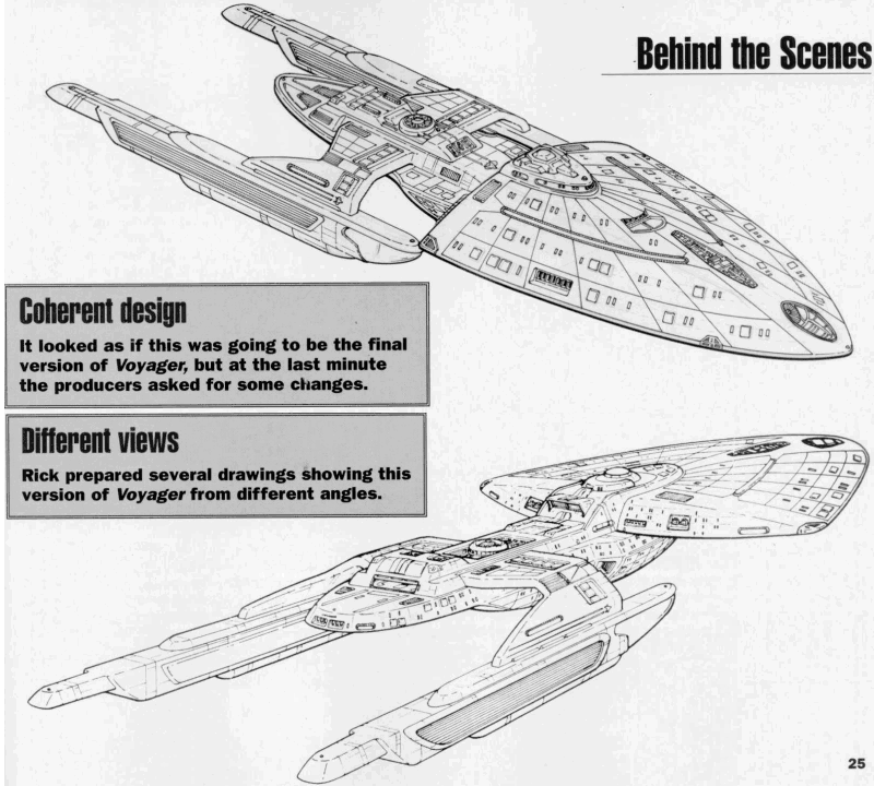
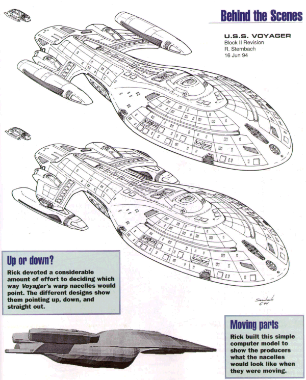
The first clean rendition of the curvy Voyager came on June 16, 1994, allowing Sternbach to continue finding
the best nacelle placement, but also showed how the smoothed hull could still be accented with interesting bits
of Starfleet hardware. This provided the positive and negative details that visual effects needed to
give the ship, through subtle surface texture and shadowing, a convincing sense of scale. Voyager contained
nearly all of the gear present in the previous angular version, only now the surface pieces hugged the hull a
bit tighter. Different items were being refined every day. With the smooth hull it was finally decided that
 Voyager would be a one-piece ship, with no separation system. If there was to be a landing on a planet, it
would be done with the entire vessel, about the size of the nuclear aircraft carrier USS Nimitz CVN-68,
crunching down on alien soil. The impulse engines were moved to the trailing edges of the pylon wings, the deck
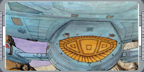
1 module was given turbolift connector tunnels and its own reaction control system thrusters. The shuttlebay at
the aft end of the engineering hull retained the flat landing deck, and gained a blended cowling over the
roll-up launch door. While concentrating on all of the little hardware details, Sternbach made one fundamental
error that took a week to catch, the deck 8 'equator' at the base of the primary hull
blithely continued on aft to become the deck 11 wing level making Voyager look oddly flat. Early in July the
final nacelle movements were completed with the 45-degree wing-up angle being approved by the producers.
Voyager would be a one-piece ship, with no separation system. If there was to be a landing on a planet, it
would be done with the entire vessel, about the size of the nuclear aircraft carrier USS Nimitz CVN-68,
crunching down on alien soil. The impulse engines were moved to the trailing edges of the pylon wings, the deck
1 module was given turbolift connector tunnels and its own reaction control system thrusters. The shuttlebay at
the aft end of the engineering hull retained the flat landing deck, and gained a blended cowling over the
roll-up launch door. While concentrating on all of the little hardware details, Sternbach made one fundamental
error that took a week to catch, the deck 8 'equator' at the base of the primary hull
blithely continued on aft to become the deck 11 wing level making Voyager look oddly flat. Early in July the
final nacelle movements were completed with the 45-degree wing-up angle being approved by the producers.
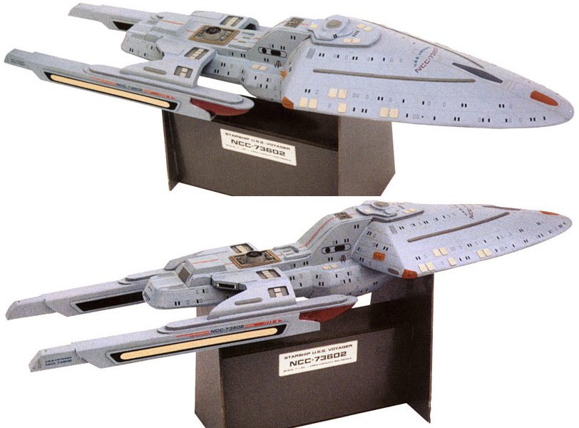
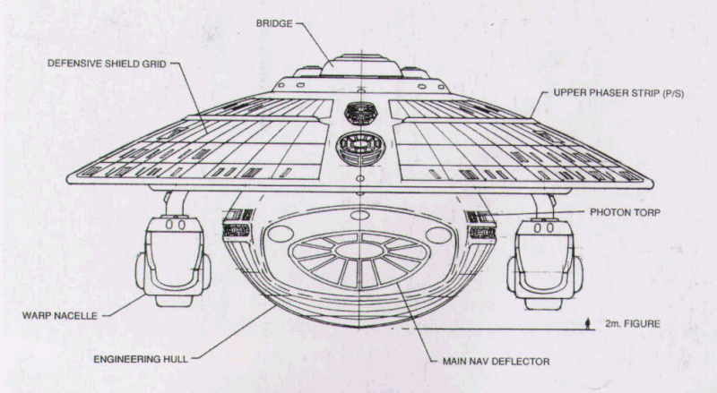
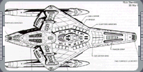
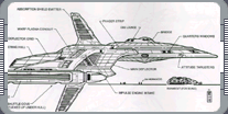
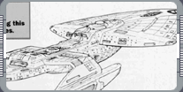
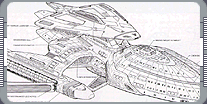
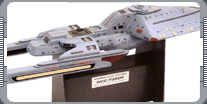
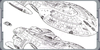
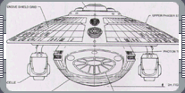 The Voyager blueprints consisted of five orthographic projections, drawn in a top and bottom plans, and
starboard, forward, and aft elevations. Since the port and starboard sides were mirror copies (the two
exceptions being the bridge and dorsal spine airlock), only half of each side was drawn and put together to form
a full view. Prior to the start of the blueprints, visual effects had decided on a five-foot long miniature,
and all drawings were done full size. Tony Meininger's Brazil Fabrication was chosen to build the model and
they were provided with all the ortho drawings and perspective sketches. Most of the unique structural elements
and starship systems were
further detailed in another set of sketches, where all important features were labeled as to supposed function,
color, or whether a lighting effect was required. As an added assist, 82 cross-section slices through the hull
and nacelles were made up by Sternbach. These allowed Meininger and his crew to build up the 3-D shapes from
sheets of 1/4" masonite and produce first-generation sculptural master parts. From those, vacuformed plastic
shells were pulled, trimmed, and detailed, and smothered in rubber molds for making the final hard resin
components. Faxes of precise drawings and quick doodles flashed between the art department and Meininger's
The Voyager blueprints consisted of five orthographic projections, drawn in a top and bottom plans, and
starboard, forward, and aft elevations. Since the port and starboard sides were mirror copies (the two
exceptions being the bridge and dorsal spine airlock), only half of each side was drawn and put together to form
a full view. Prior to the start of the blueprints, visual effects had decided on a five-foot long miniature,
and all drawings were done full size. Tony Meininger's Brazil Fabrication was chosen to build the model and
they were provided with all the ortho drawings and perspective sketches. Most of the unique structural elements
and starship systems were
further detailed in another set of sketches, where all important features were labeled as to supposed function,
color, or whether a lighting effect was required. As an added assist, 82 cross-section slices through the hull
and nacelles were made up by Sternbach. These allowed Meininger and his crew to build up the 3-D shapes from
sheets of 1/4" masonite and produce first-generation sculptural master parts. From those, vacuformed plastic
shells were pulled, trimmed, and detailed, and smothered in rubber molds for making the final hard resin
components. Faxes of precise drawings and quick doodles flashed between the art department and Meininger's
 shop. Effects producer Dan Curry called for tiny backlit film frames of the sets to be placed in the miniature
to give the illusion of the rooms seen through the glass (or is it transparent aluminum?). In cases where an
exact hull contour couldn't be puzzled out in all three dimensions, Meininger went for a hands-on sculptural
solution as the parts were being shaped, and the results were always very close to what the drawings intended.
Cross-sections through some areas were used to confirm how heights and angles changed within various structures,
most importantly in the bridge, mess hall, and captain's quarters. The outline shape of the aeroshuttle was
finalized and mapped to the primary hull underside.
shop. Effects producer Dan Curry called for tiny backlit film frames of the sets to be placed in the miniature
to give the illusion of the rooms seen through the glass (or is it transparent aluminum?). In cases where an
exact hull contour couldn't be puzzled out in all three dimensions, Meininger went for a hands-on sculptural
solution as the parts were being shaped, and the results were always very close to what the drawings intended.
Cross-sections through some areas were used to confirm how heights and angles changed within various structures,
most importantly in the bridge, mess hall, and captain's quarters. The outline shape of the aeroshuttle was
finalized and mapped to the primary hull underside.
Colors were specified and passed through visual effects to confirm the modelmakers that Voyager would be a
recognizable Starfleet blue-gray overall, with accents of other established colors. Paint specs were
transmitted for the phaser strips, RCS thrusters, escape pod hatches, and all other visible equipment, usually
in warmer tones for contrast. Senor arrays were pegged in metallic blue and copper. Formation lights appeared
 in red, green, and white. Mike Okuda worked up sheets of dry-transfer hull markings for the ship name and
registry number, as well as Starfleet pennants and hundreds of warning strips and tiny access hatches. Voyager
was moving toward its first days of effects filming at Image-G when the producers requested the last two surface
changes; one to add a bit of variation in the hull plate shading or weathering, the other to add some raised
strips to break up the smooth curves and which became structural integrity field reinforcements. Meininger was
given a map of the reinforcement strips, the final painting was done, and the miniature starship went to work.
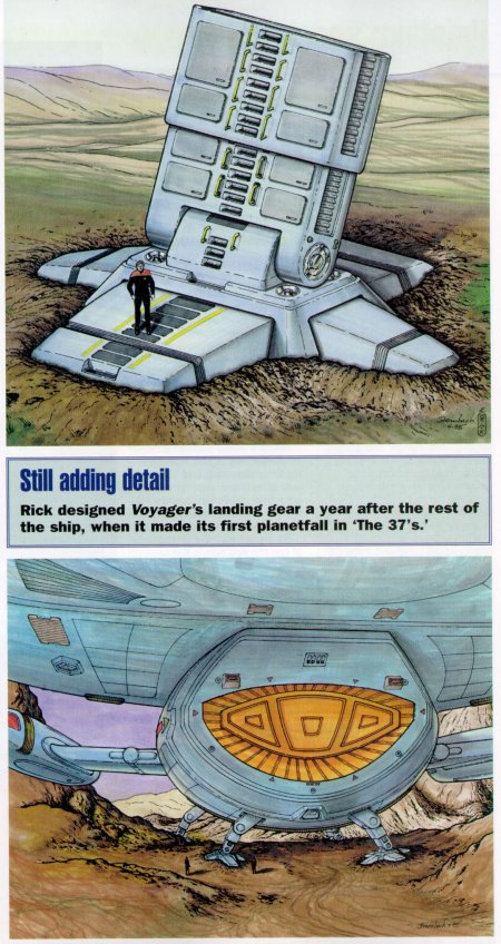
The ship was photographed on the motion-control rig, and was even measured and scanned for 3-D digitizing into a
CGI model. In May of 1995 work began on "The
37's" which was the first time Voyager would land on a planet, and so the landing gear finally had to be
engineered. While the ship was intended to land, only the gear hatches had been designed with no plans yet on
the rest.
in red, green, and white. Mike Okuda worked up sheets of dry-transfer hull markings for the ship name and
registry number, as well as Starfleet pennants and hundreds of warning strips and tiny access hatches. Voyager
was moving toward its first days of effects filming at Image-G when the producers requested the last two surface
changes; one to add a bit of variation in the hull plate shading or weathering, the other to add some raised
strips to break up the smooth curves and which became structural integrity field reinforcements. Meininger was
given a map of the reinforcement strips, the final painting was done, and the miniature starship went to work.
The ship was photographed on the motion-control rig, and was even measured and scanned for 3-D digitizing into a
CGI model. In May of 1995 work began on "The
37's" which was the first time Voyager would land on a planet, and so the landing gear finally had to be
engineered. While the ship was intended to land, only the gear hatches had been designed with no plans yet on
the rest.
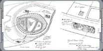 Packing an articulated set of legs and footpads in a space only 13 feet high was something of a challenge.
Everything had to neatly fold out and support some fraction of Voyager's 750,000 metric tons, the bulk of the
mass held off the ground by impulse engine fields. Sternbach's initial sketches depict legs with a single
footpad, but eventually a set of folding toes to distribute the pressure. Jefferies tube access to the ground
was added, along with steps and handrails. While a full-size footpad couldn't be built for location shooting,
miniature feet were fabricated for some static shots, and the 'real' gear deployment and touchdown was captured
in computer animation. Since then, a few more previously unseen parts have been added to Voyager, like the
complete warp core and the escape pods. It's hull has been torn up and covered in Borg plating, and totally
destroyed. As Voyager continues on its trajectory back to Earth, it's difficult to imagine any other starship
that has endured the hardships and survived.
Packing an articulated set of legs and footpads in a space only 13 feet high was something of a challenge.
Everything had to neatly fold out and support some fraction of Voyager's 750,000 metric tons, the bulk of the
mass held off the ground by impulse engine fields. Sternbach's initial sketches depict legs with a single
footpad, but eventually a set of folding toes to distribute the pressure. Jefferies tube access to the ground
was added, along with steps and handrails. While a full-size footpad couldn't be built for location shooting,
miniature feet were fabricated for some static shots, and the 'real' gear deployment and touchdown was captured
in computer animation. Since then, a few more previously unseen parts have been added to Voyager, like the
complete warp core and the escape pods. It's hull has been torn up and covered in Borg plating, and totally
destroyed. As Voyager continues on its trajectory back to Earth, it's difficult to imagine any other starship
that has endured the hardships and survived.
|
|
"DESIGNING THE U.S.S. VOYAGER" - NOVEMBER 2000 ISSUE 19 STAR TREK: THE MAGAZINE
"DESIGNING STAR TREK: VOYAGER" - JULY 2001 ISSUE 28 STAR TREK: THE MAGAZINE
COPYRIGHT OF PARAMOUNT PICTURES.
|